
 Português
How to Calibrate a Bucking Unit?
Browse services
- Petroleum and Gas
- Egypt Petroleum Show
- Beijing Petroleum & Petrochemical Exhibition
- Foreign Business Representatives Visit and Guide
- Jiangsu Shenlida Machinery Manufacturing Co., Ltd. made its debut at the Abu Dhabi Petroleum Exhibition
- What are the advantages of using a Bucking Unit?
- Common Bucking Unit Operation Errors and How to Avoid Them?
- What are the safety checks before operating a Bucking Unit?
- Bucking Unit Safety Operating Procedures
- How to Use the Operator Panel to Control a Bucking Unit
- How to Calibrate a Bucking Unit?
- What preparations are needed before using the Bucking Unit?
- What is the operating procedure of the Bucking Unit?
21 Aug
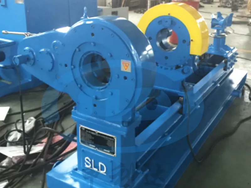
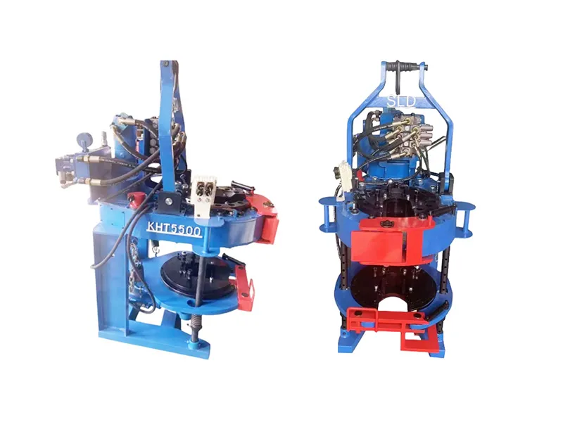
A bucking unit (tightening unit or torque unit) is a key component of many industrial manufacturing equipment, particularly in cable manufacturing, wire processing, and automotive assembly. It provides precise torque output for tightening operations or torque control, ensuring product quality and assembly reliability. With the advancement of industrial automation, the performance of the bucking unit is directly related to equipment stability and processing accuracy.
However, as equipment ages or process adjustments are needed, bucking unit performance may deviate, leading to inaccurate torque control and compromising product quality. Therefore, regular bucking unit calibration is crucial. This article will detail the bucking unit calibration process and key technical points to help operators and maintenance engineers master scientific and efficient calibration methods.
The Importance of Bucking Unit Calibration
Ensuring Torque Accuracy
The core function of a bucking unit is to generate accurate torque. Calibration eliminates or compensates for errors caused by factors such as mechanical wear, sensor drift, and electrical interference, ensuring that torque output meets specified requirements.
Improving Product Quality
Accurate torque control is essential for ensuring the quality of fastening joints, preventing overtightening or undertightening, which can lead to product failure or safety hazards. Extending Equipment Life
Calibration allows for timely detection of anomalies, preventing equipment damage from overload or malfunction, and reducing maintenance frequency and costs.
Meeting Quality Management System Requirements
Many manufacturers are required to comply with quality certification standards such as ISO and TS. Regular calibration of bucking units is a key component of compliance checks.
Pre-Calibration Preparation
1. Understanding Equipment Specifications and Calibration Standards
First, carefully review the bucking unit's technical manual and the manufacturer's calibration guide to clarify the calibration specifications, tolerances, calibration frequency, and methods. Calibration specifications may vary for different bucking unit models and applications.
2. Preparing Calibration Tools and Equipment
Calibration typically requires a high-precision torque calibrator, torque wrench, signal acquisition equipment, and data analysis software. Ensure all instruments are in effective calibration to prevent tool errors from affecting the results.
3. Environmental Preparation
The calibration environment should be clean, vibration-free, and maintain a moderate temperature and humidity to prevent environmental factors from interfering with test data. Ensure the equipment is powered off and that there are no strong electromagnetic interference sources nearby. 4. Personnel Preparation
Assign technicians with professional knowledge and operational experience to perform the calibration work to ensure proper operation and accurate data.
Bucking Unit Calibration Steps
1. Initial Inspection and Equipment Cleaning
Disconnect the power and control signals to the bucking unit and confirm that the equipment is in a safe state.
Inspect the bucking unit's mechanical components for obvious wear, looseness, or damage. Clean dust and lubricant from key areas such as bearings and gears to ensure smooth mechanical transmission.
2. Connecting the Calibration Instruments
Install a high-precision torque sensor at the bucking unit's output or designated test point, ensuring a secure connection.
Connect the data acquisition equipment, set the sampling frequency and parameters, and prepare to record torque signals.
3. Setting the Calibration Procedure
According to the equipment manual, set the standard operating parameters for the bucking unit, such as speed, load torque, and operating time.
Configure the calibration software and establish calibration reference points based on a standard curve or historical data.
4. Performing the Initial Torque Output Test
Start the bucking unit and gradually increase the load torque from zero to maximum operating torque, collecting data at multiple points. Record the torque sensor reading and the torque value displayed by the Bucking Unit control system, and compare the difference.
5. Data Analysis and Error Calculation
Use data processing software to compare the torque output signal with the standard value and calculate the error percentage for each test point.
Confirm that all data points are within the allowable error range.
6. Adjustment and Compensation
If the error is found to be outside the allowable range, adjust the sensor zero point, amplification factor, or software compensation parameters based on the Bucking Unit's structural characteristics.
Perform fine-tuning on the mechanical components, such as adjusting tension, checking lubrication conditions, and correcting transmission mechanism clearance.
7. Secondary Test and Confirmation
After adjustments are completed, perform the torque output test again to ensure that the error has been effectively corrected.
Repeat the test multiple times to ensure that the data is stable and meets the standard.
8. Complete Calibration and Generate a Report
Save all test data and generate a calibration report that includes the calibration date, instrument model, test results, adjustment process, and conclusions.
If necessary, input the calibration results into the equipment control system for automatic compensation.
Key Technical Points in Calibration
1. Torque Sensor Selection and Installation
The accuracy of the torque sensor directly affects the calibration results. Select a sensor that meets the specified accuracy level (generally 0.1 or higher) and avoid axial offset and bending moment interference during installation to ensure accurate measurement data.
2. Load Uniformity
During calibration, the applied load should be uniform and stable to avoid sudden changes and vibration that may affect the test. Use a dedicated load device or a standard torque wrench to assist in applying force.
3. Temperature and Environmental Influences
The performance of the torque sensor and bucking unit is sensitive to temperature. The calibration environment should be as stable as possible, and temperature compensation should be performed if necessary.
4. Data Acquisition and Processing
The sampling frequency should be high enough to capture detailed torque fluctuations. During data processing, use a filtering algorithm to eliminate outliers and ensure accurate analysis results.
Common Problems and Solutions
1. Excessive Calibration Result Error
Possible Causes: Improper sensor installation, severe wear of mechanical components, or incorrect software parameter settings.
Solution: Recheck sensor installation, perform mechanical maintenance, and verify software settings.
2. Unstable Torque Output
Possible Causes: Drive motor malfunction, loose drive belt, insufficient lubrication.
Solution: Repair the motor, adjust belt tension, and add lubricant.
3. Signal Interference or Abnormal Data
Possible Causes: Electromagnetic interference, poor sensor wiring contact.
Solution: Strengthen shielding measures, check cable connections, and use filters.
4. Improper Calibration Schedule
It is recommended to establish a reasonable calibration schedule based on equipment usage frequency, load conditions, and production requirements to avoid performance degradation due to inadequate calibration.
Recommended Products


Contact US
Product Information
Quantity
Unit
Piece
Support order samples, customization, wholesale direct, and complete payment. If the product you look for does not have corresponding customized content, pls fill out the form below to contact us, and we will reply ASAP.